Electrical Content#
Alex Valdes, Purdue University Last Modified: 2026-01-23
Given that this course has only 20001 and 20007 as prerequisites, this page will cover any additional content that could be useful for your lab content. All of this content is designed to help you fill in gaps and get you investigating further into your devices, so many details are glossed over or simplified for a working understanding rather than an in depth explanation of these devices.
Semiconductors#
How to Read an IC#
ICs, or integrated circuits, are prepackaged circuits that will be used in every electronic device. When working around ICs, it’s important to be able to identify which pins are where to better understand the circuit. Below is an image showing how ICs are labeled so you can better count the pins on your ICs.

Image Source: Instructables
Diodes#
Diodes act as one directional switches, allowing current to flow in one direction when turned on. Most diodes are activated by a forward voltage, or the input voltage to the diode being large enough to allow electrons to overcome the bandgap built into the semiconductor within.
Diodes, by virtue of the unidirectional conducting, can act to effectively remove components of a signal that are less than the forward voltage. This allows diodes to be used in AC circuits to remove the negative components, creating a purely positive signal. More advanced diode configurations, like a full bridge rectifier, can be used to effectively invert the negative component of an AC signal into a positive component, creating an |sin| wave.
Transistors#
Transistors are the backbone of modern technology. While they are what make microprocessors function, they have been around for far longer than the modern computer and exist in a few key forms.
MOSFET#
The MOSFET, or Metal-Oxide semiconductor field effect transistor is a transistor composed of a gate, drain and source. The gate is the terminal where a control voltage will allow conduction through the transistor, with the drain and source being the path the current will travel through. There are P type and N type MOSFETs. P type allow conduction with a low gate voltage, while N type require a high gate voltage.
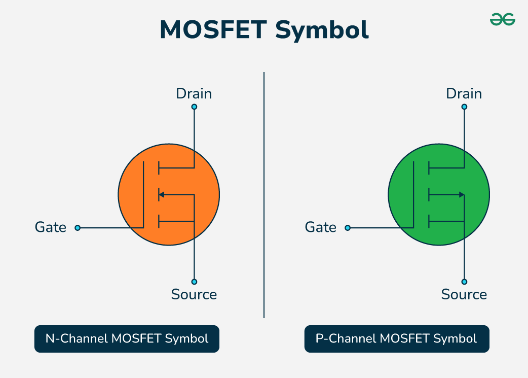
Image source: GeeksforGeeks
BJT#
A BJT, or bipolar junction transistor, is a transistor that is composed of the base, the terminal where the controlled current goes to adjust current conduction through the device, the emitter, and the collector. NPN BJTs are designed to allow current flow from collector to emitter and PNP are designed to allow current flow from emitter to collector.

Image Source:GeeksforGeeks
Transistor Circuits#
For this course, most often you will encounter transistors being used as a switch or for current regulation. Switching circuits take advantage of the required gate voltage or base current to act as an electronically controlled switch within a circuit, either disconnecting entire portions of the circuit or used in specific schemes to create unique signals. Current regulation circuits use the gain characteristics of a transistor, or it’s ability to allow more power to flow through the terminals than required to turn on the device, to deterministically control the current characteristics of a circuit without changing external components. An example of each is shown below.
H Bridge#
An H bridge, named after the H like shape created by the transistors, is a transistor array that can be used to create time varying signals with positive and negative components.
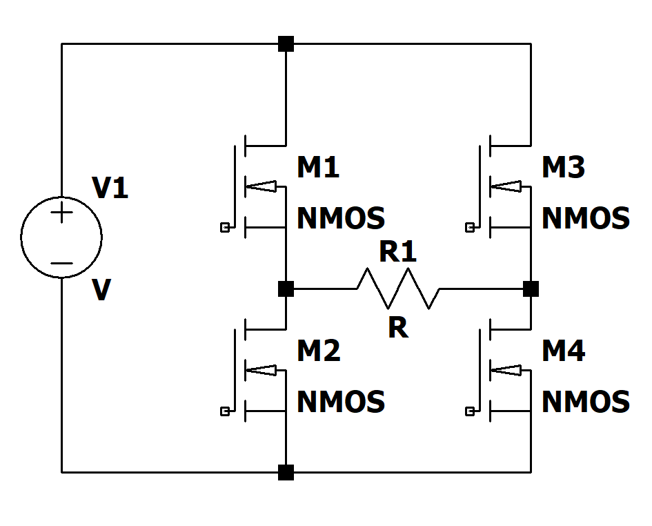
When transistors 1 and 4 are turned on, 2 and 3 are turned off, creating only one path through the circuit, creating a positive voltage drop across the resistor load. When 2 and 3 are on, and 1 and 4 are off, a negative voltage is dropped across the load, creating a negative segment to the output signal. When controlled precisely, specific wave shapes, like a sine wave, can be created.
Current Mirror#
A current mirror, sometimes a current follower, is a specific transistor circuit that utilizes at least two transistors. One transistor has the input and gate/base connected with the input calibrated to supply a specific amount of current. This connection will bias the transistor to output the specific current, here shown as IREF, through M1. M2 has it’s gate tied to the gate of M1, allowing M2 to be set to a matching current throughput.
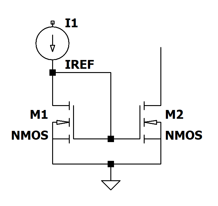
Current mirrors are used to control the output current of a system regardless fo the load attached to the M2 transistor. This system can be utilized with multiple transistors in parallel to create current multipliers, common in IC design to create current gain.
The “Do Everything” Chips#
There are many times in this course when you will encounter what we like to call “Do Everything” chips. These chips are often contain multiple subsystems that do most of the heavy lifting for a circuit and make the circuit properly function. Working through these chips can be difficult, especially if it has no idenfitying text, schematic can’t be found, or is covered in the forbidden goo.
One strategy to decypher these chips is to answer these questions:
What is the circuit missing?
If you expected a certain device in a circuit, like some form of voltage regulation, could the chip be that device?
What is it connected to?
Is the chip only connected to a USB port? Then it’s likely a USB controller. If it is only connected to one subsystem, it is likely integral to that subsystem alone, like a driver or controller of some kind.
Can I probe it’s pins safely?
Probing these devices can often prove very useful. Of note, if the device is wall powered, you should ask the teaching staff if it’s safe to probe, and it likely requires some additional work to prepare to probe at 120V AC signals.
Thermal Regulation#
When dealing with high power devices, thermal regulation is a serious consideration. We know that resistors consume power equal to the current passing through them multiplied by the voltage dropped across them, but where does this power go? This power is released as heat. Another fact we know is everything has a little bit of resistance, even a copper wire. When powering high power draw devices, there tends to be a lot of heat trapped in the device due to small inefficiencies within each of the components. To manage this, many devices add heat sinks, or pieces of metal bonded to the heat generating components, to act as a place for the heat to flow so it can better be disappaited into the air. These heat sinks are most commonly seen attached to microprocessors, light emitting diodes, or power regulation circuitry, like an LDO.
The Op Amp#
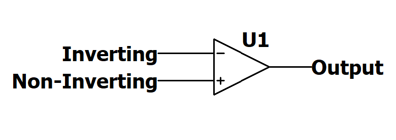
Op-amps, or operational amplifiers, are the Swiss Army Knife of electronics. Op amps utilize two input ports, a non-inverting (+) and an inverting input (-) and drive the output high or low depending on the voltage levels at each input. If the inverting input is larger, the output is driven low, and if the non-inverting is larger then the output is driven high. This op-amp setup is used to compare different signals and create binary outputs of high and low based on the changing of the input conditions.
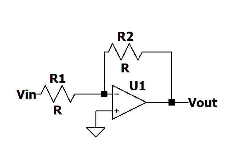
Another use for op-amps are as gain steps. Utilizing a feedback loop, or a loop connecting the output to the inverting or non-inverting input through some passive component, a deterministic gain can be achieved on the output, allowing for signal amplification. These can also be used with capacitors in the loop to create differentiating or integrating gains, useful in control systems.
Low Pass Filters#
Low pass filters are a tool used in almost every device to smooth out a waveform. Low pass filters work by passing a time variable signal through a resistor and capacitor in series, causing the higher frequency signals to be attenuated, or decreased in amplitude, due to the capacitor decrease it’s impedance as freqency increases.
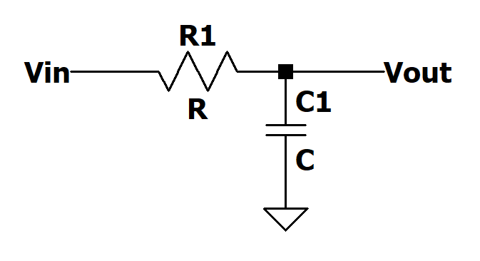
Low pass filters are used in many places, often as a step after a diode rectifier, allowing the rectified signal to be even closer to a DC signal. They are also used to remove high frequency noise from an information signal to avoid artifacts in the output.
Citations#
https://www.instructables.com/Integrated-Circuits-1/
https://www.geeksforgeeks.org/electronics-engineering/mosfet-characteristics/
https://www.geeksforgeeks.org/electrical-engineering/difference-between-bjt-and-fet/